Rain Water Harvesting System Diagram

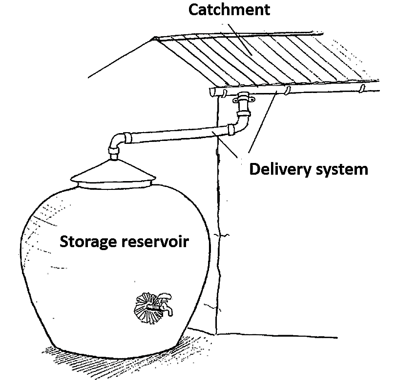
It may be a terrace courtyard or paved or unpaved open ground.
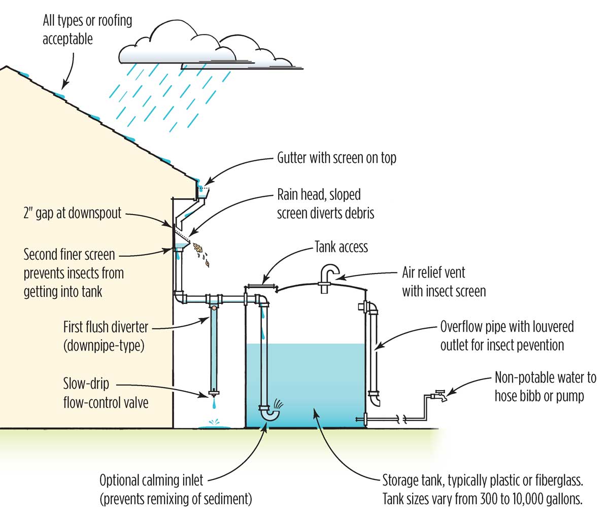
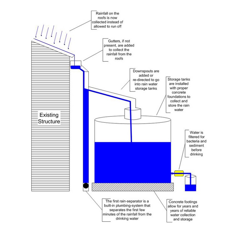
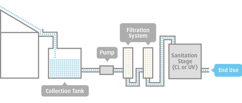
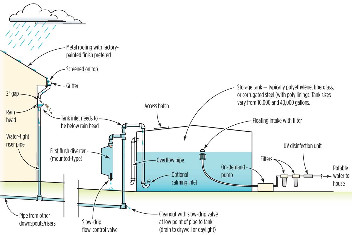
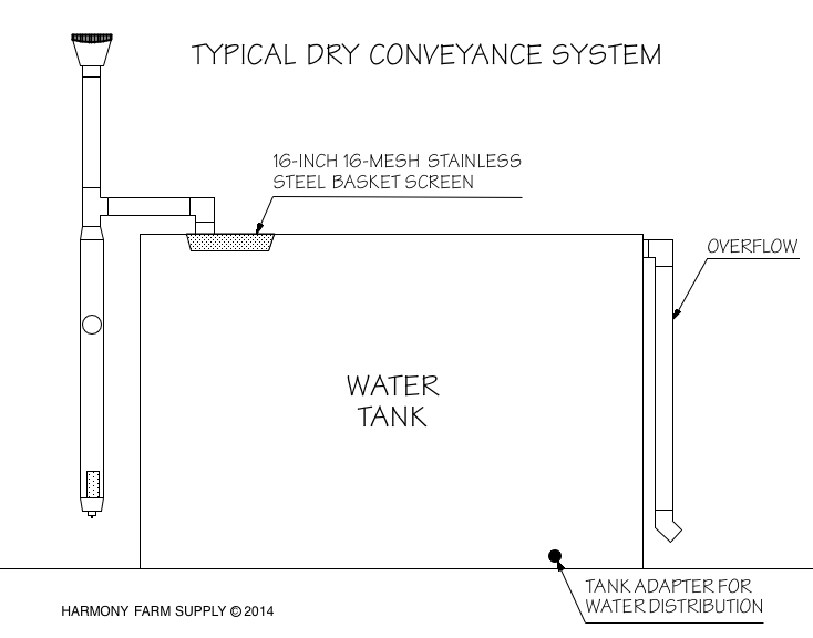
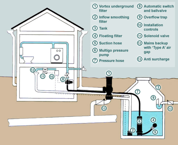
Rain water harvesting system diagram. Rainflo 10 000 gallon rainwater harvesting system with corrugated steel tank optimax industrial pre filter and mhp75a automatic pump ref. The diagrams below shows the typical schematic layout of a rainwater harvesting system which supplies water under pump pressure direct from the. Understanding the operating principles of rwh systems is essential to ensure their successful installation. It can be a paved area like a terrace or courtyard of a building or an unpaved.
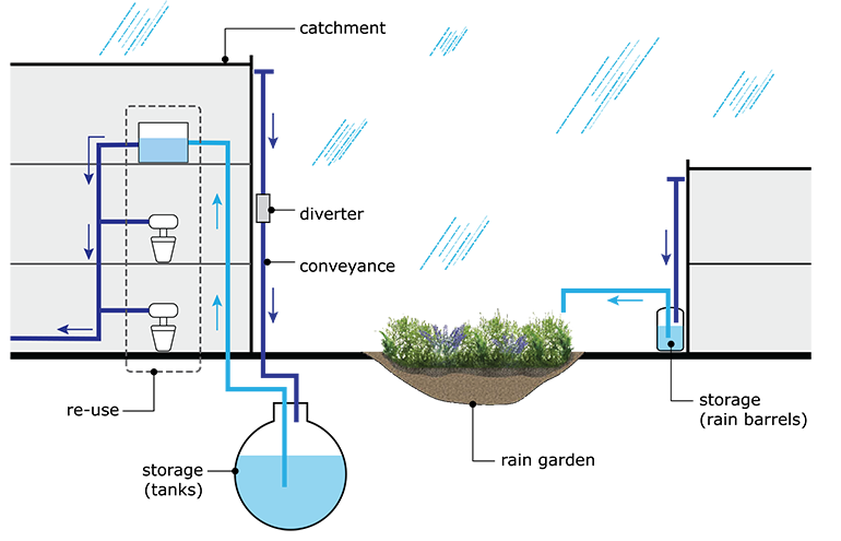
Therefore the catchment is the area which actually contributes rainwater to the harvesting system. Rainwater is collected from a roof like surface and redirected to a tank cistern deep pit well shaft or borehole aquifer or a reservoir with percolation. Rainflo carat s 12 000 gallon complete rainwater harvesting system with 2 optimax industrial filters and rainflo pump system ref. Rainwater harvesting rwh the collection and storage of rain rather than allowing it to run off.
Rainwater groundwater toilet flushing cooling tower makeup above ground tank city water pressure building pump pressure rucbih underground tank groundwater sump and treatment skid rainwater treatment above ground plastic tank cces building pump solenoid connection to building pump inlet. System components 6. The common components of a rainwater harvesting system involved in these stages are illustrated here. The surface that receives rainfall directly is the catchment of rainwater harvesting system.


